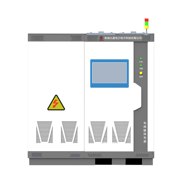
JHT series power grid simulation power supply system
Product Overview
The JHT Series Grid Simulation Power System is a high-precision (voltage accuracy ≤±0.1%, frequency accuracy ≤±0.001Hz), high-dynamic (response time 1ms), full-featured grid simulation power source specifically designed for grid adaptability testing of converters in energy storage, photovoltaic, and other renewable energy industries. Utilizing advanced digital control technology (supporting software programming and real-time adjustment), it enables four-quadrant operation (supporting bidirectional energy flow) and comprehensive simulation from "ideal grid" to "extreme adverse grid" conditions, specifically addressing stringent testing requirements for renewable energy converters in scenarios such as grid connection impact, harmonic tolerance, and frequency ride-through.
Product Features
High-Precision Simulation:
Features sine wave output and multiple harmonic superposition modes, capable of simulating various grid states including over/under voltage, over/under frequency, three-phase imbalance, and voltage ride-through.
Four-Quadrant Operation:
Supports bidirectional energy transfer, reducing energy consumption and operational costs.
Intelligent Testing:
Employs 32-bit floating-point DSP digital technology for intelligent testing processes with strong programmability.
Comprehensive Testing Functions:
Includes high/low (zero) voltage ride-through, step, sag, flicker, and other test functions, supporting 1ms ride-through testing.
Advanced Monitoring:
Real-time monitoring of key parameters such as IGBT temperature and transformer temperature, with complete data logging to reduce maintenance time.
Multiple Communication Interfaces:
Equipped with CAN2.0A/B, RS485, Ethernet interfaces, with optional RS232 and GPIB interfaces to meet diverse communication needs.
Application Scenarios
Renewable Energy Equipment Testing:
Grid-connected/off-grid performance verification of PV inverters and energy storage converters (PCS), MPPT efficiency analysis;
Electric Vehicle Sector:
Charge/discharge characteristics and grid adaptability testing of onboard chargers (OBC) and charging piles;
Power Electronics R&D:
Dynamic response and fault simulation of frequency converters and UPS power supplies;
Smart Grid Simulation:
Microgrid stability analysis, power quality disturbance simulation (e.g., flicker, frequency deviation).
Typical Equipment Parameters and Models
Typical Equipment Models | ||||||
Model | Rated Power (kVA) | Voltage Range (V) | Frequency Range (Hz) | Max Current per Phase (A) | Weight (kg) | Dimensions (W×D×H/mm) |
JHT-063F-4Q | 63 | 0~470 | 40~70 | 150 | 240 | 1000×1000×1500 |
JHT-100F-4Q | 100 | 0~470 | 40~70 | 200 | 300 | 1000×1000×1500 |
JHT-150F-4Q | 150 | 0~470 | 40~70 | 400 | 400 | 1000×1000×1900 |
JHT-240F-4Q | 240 | 0~470 | 40~70 | 450 | 500 | 1140×1000×1900 |
JHT-320F-4Q | 320 | 0~470 | 40~70 | 500 | 2400 | 1140×1000×1900 |
JHT-630F-4Q | 630 | 0~900 | 40~70 | 900 | 4500 | 5840×1200×1900 |
JHT-1000F-4Q | 1000 | 0~900 | 40~70 | 1000 | 6800 | 7840×1200×1900 |
System Parameters | ||||||
Load-Side Parameters | Load Output Mode | Three-phase four-wire output, each phase independently controllable | ||||
Voltage | Line voltage AC0V~900V | |||||
Frequency | 40Hz~70Hz | |||||
Setting Accuracy | Voltage | Resolution: 0.01V, Accuracy: 0.1% of full scale | ||||
Frequency | Resolution: 0.001Hz, Accuracy: 0.01% | |||||
Measurement Accuracy | Voltage | Resolution: 0.01V, Accuracy: 0.1% of full scale | ||||
Frequency | Resolution: 0.001Hz, Accuracy: 0.01% | |||||
Current | Resolution: 0.1A/1A, Accuracy: 0.2% of full scale | |||||
Power | Resolution: 0.1kW/0.01kW/0.001kW, Accuracy: 0.3% of full scale | |||||
Frequency Stability | ≤0.01% | |||||
Voltage Distortion | THD:<1% for="" linear="" loads=""> | |||||
Response Time | 1ms | |||||
Three-Phase Phase Difference | Standard three-phase mode: 120°±0.3° | |||||
Unbalanced mode: 0.0°~359.9°, adjustable in 0.1° steps | ||||||
Phase Voltage Crest Factor | 1.41±0.1 | |||||
Source Effect | ≤0.05% | |||||
Load Effect | ≤0.05% | |||||
Overload Capacity | 100%<o(jì)utput≤110%: 600s shutdown; 110%<o(jì)utput≤150%: 60s shutdown; 150%<o(jì)utput≤200%: 2s shutdown; 200%<o(jì)utput: immediate shutdown. | |||||
Protection Measures | IGBT overtemperature, IGBT overcurrent, transformer overtemperature, input over/under voltage, bus over/under voltage, output over/under voltage, output phase loss, overcurrent, overload, short circuit | |||||
Functional Modes | Display Method | Backend computer display | ||||
Output Waveform | Sine wave, harmonics (superimposed 2nd~50th order), interharmonics | |||||
Transient Mode | Supports voltage step (sag) from high to low or low to high | |||||
Flicker Mode | Supports calling any of 1~39 sets of flicker parameters | |||||
High/Low Voltage Ride-Through Mode | Supports standard curves or user-customized adjustments | |||||
Unbalance Mode | Allows independent adjustment of three-phase voltages and phase differences or direct setting of unbalance degree | |||||
Programming Mode | 200 steps with 999,999 cycles, programmable voltage, frequency, and phase angle output | |||||
Soft Start Time | 0.0~99.9 seconds | |||||
Online Adjustment | In normal mode, allows online adjustment of output voltage, frequency, and waveform switching | |||||
Memory Function | Power-off memory retains last output mode and parameters | |||||
Communication Interfaces | CAN2.0A/B, RS485, RS232 (optional), GPIB (optional), Ethernet (standard), sync signal (standard) | |||||
Parallel Function | Supports parallel operation of 4 or more units | |||||
Environmental Requirements | Temperature | -10~40℃ | ||||
Humidity | 10~90%RH | |||||


